Practical Reversing: Fanlight 01 - Overview and Teardown
Preface
This set of posts will cover my experience reverse engineering a Fanlight pen light product. I initially went through this exercise as a fun way to provide some knowledge to "my kids." I'm a mentor for a high school robotics team. Any chance I get, I love to bring knowledge to them about how the world of technology works.
I wanted to use this particular product to provide an overview of how today's IoT things work, both in a "how they're made" sense, as well as a "how they break" sense. This meant I approached the product with a very wide lens. I wanted to cover BLE and memory-mapped-interfaces; AWS and PWM. Just a whole smattering of things that are off in different corners. I'll do my best to migrate those scatter-brained notes to a somewhat coherent set of posts.
Thank you KoiBots for being such an engaged audience with my initial presentation. You all continue to inspire me to keep tinkering.
Thank you random reader for joining me on this adventure.
And finally, "thanks DXTEEN."
A Vacation
In January 2025 my wife and our oldest cat finalized their move from the USA to Japan. I took a much-too-short trip to help get the cat settled and build some furniture. While in Japan, I also joined Naomi on one of her Oshikatsu adventures where we went to the Tokyo Dome to see Lapone's 2025 Laposta premier event.
It was here in one of the merch lines, that I picked up the subject of this set of posts.
Naomi and I were excited about this device for entirely different reasons.
This sort of product is used to by fans to show their love and excitement for their favorite group, and often a specific member out of that group. Fanlight's devices go a bit further than just rotating through some RGB options. They have a companion Android / iOS app that enables all kinds of goodies over Bluetooth.
Features:
- Regular pushbutton to rotate through predefined colors
- Naomi's got hers always set to green
- App: Set arbitrary colors
- App: Join a livestream for a specific event
- YouTube link showing off this capability
Naomi and I each bought a pen light and had a blast at the concert. All of the lights in the crowd made for a really fun spectacle. I'm also a sucker for pyrotechnics; at one point one idol group exploded into flames and another took their place. Great experience, would scream for idols again.
One long, sad plane ride later I was back in the states and had a new toy to take apart.
The Teardown
So... I never really learned the proper way to open up one of these. There's no glue or screws holding any of the plastic components together. There are instead dozens of cantilever snap fit points that make the device tricky to open.
Breaking In
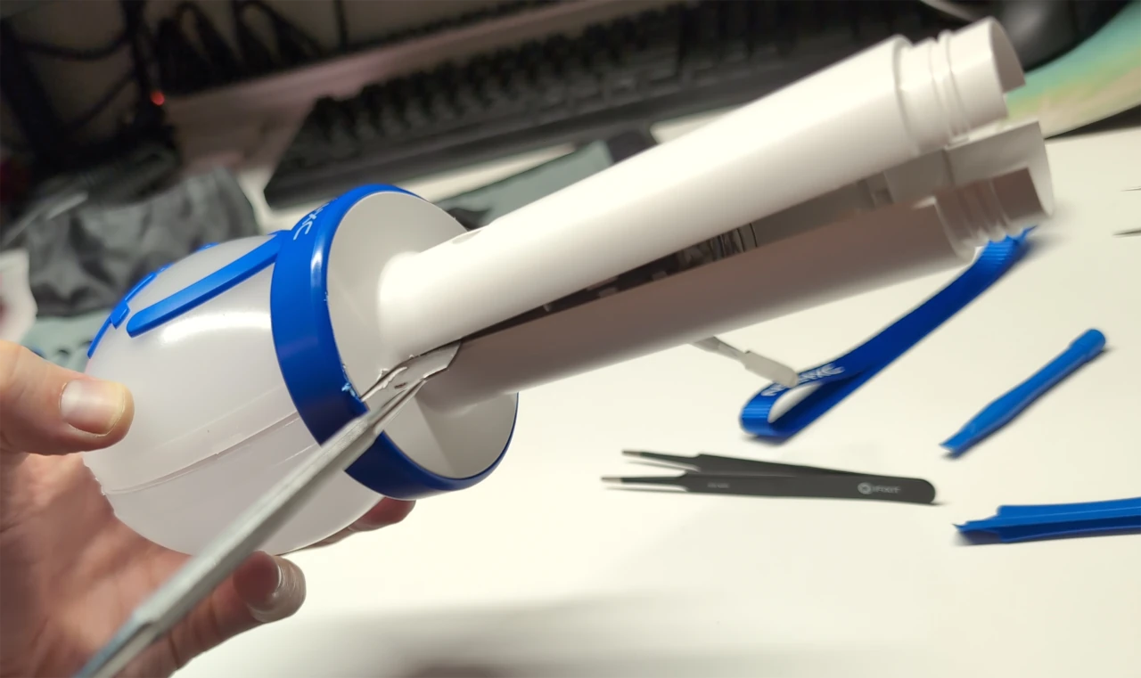
I gave this a really solid attempt.
Like, at least a half hour of scratching my head and squinting at the problem.
Eventually, however...
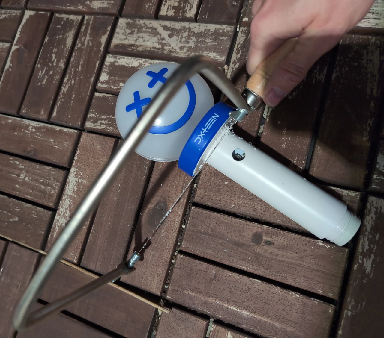
Tada!
Okay, we got it open! Time for some beauty shots of our model. These photos were taken with a Sigma 10-18mm F2.8 DC DN lens on a Sony Alpha α6400. The images were then brought into GIMP to resize and compress them.
Image Gallery
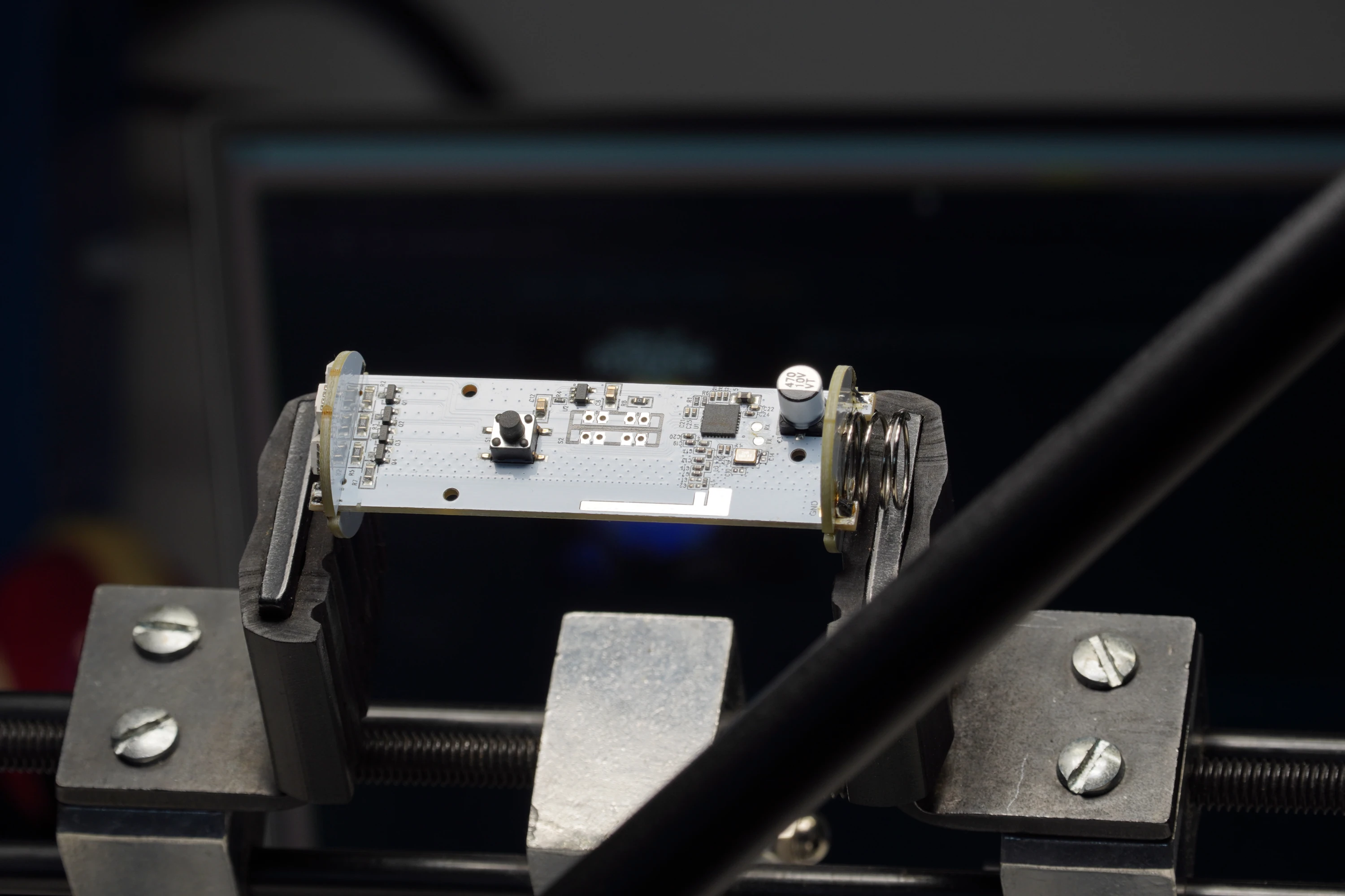
Initial Triage
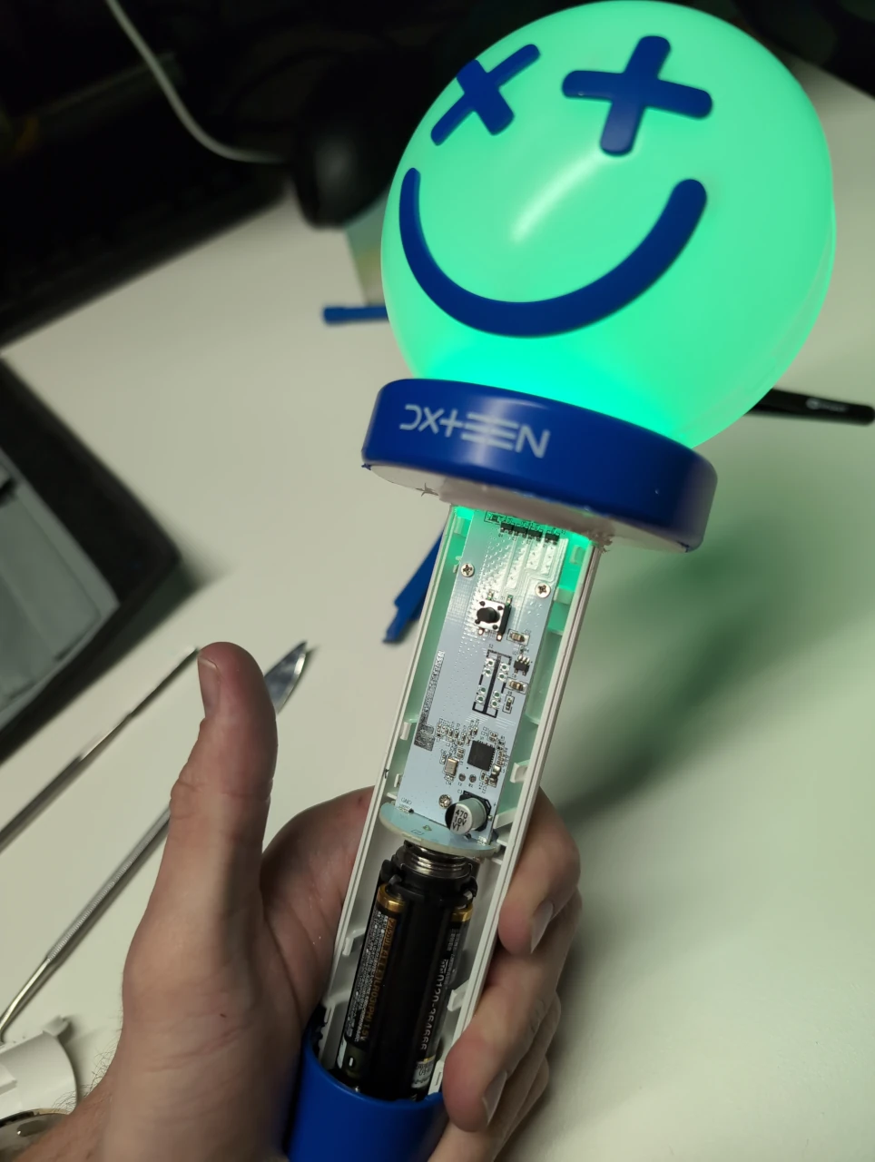
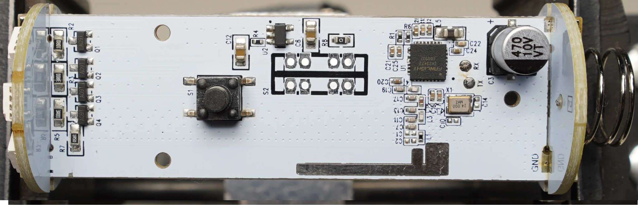
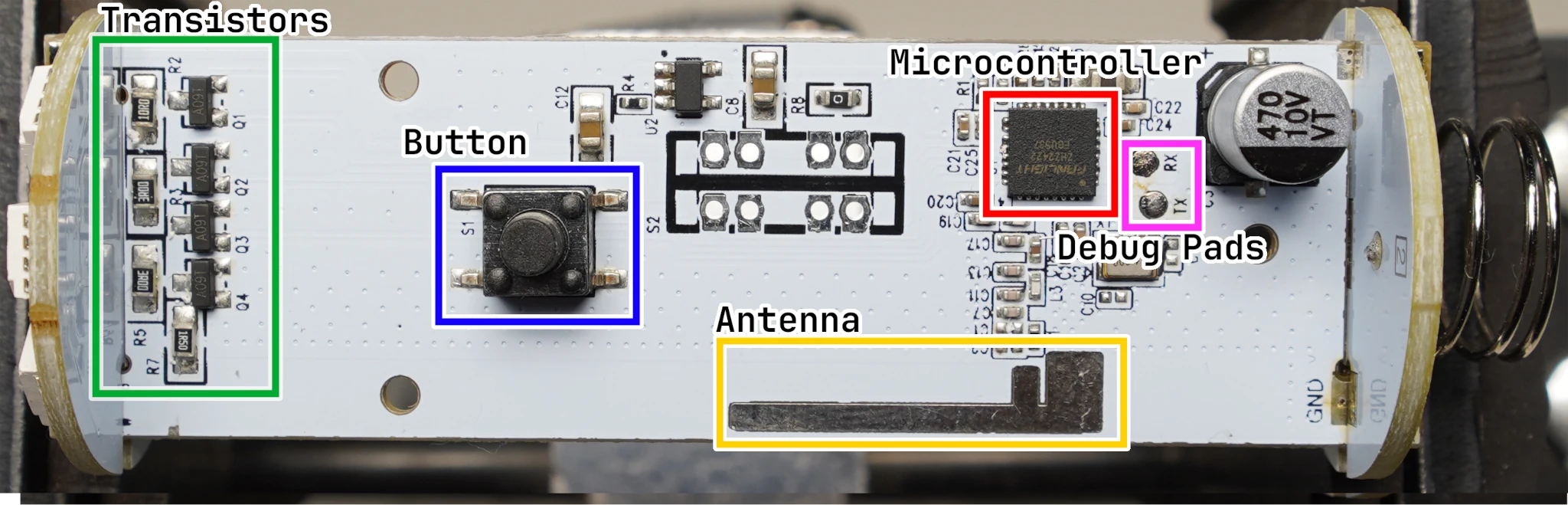
The PCB is pretty simple. Power comes in through the right-hand side, LEDs shoot photons out of the left-hand side.
We can see a singular microcontroller with supporting passives and a 24 MHz clock nearby. There are two debug pads labelled RX
and TX near the MCU. Don't mind the flux that's burned on to the pads, I took these pictures after working on the board.
We've also got an antenna just south of the MCU, which would make sense with the BLE features.
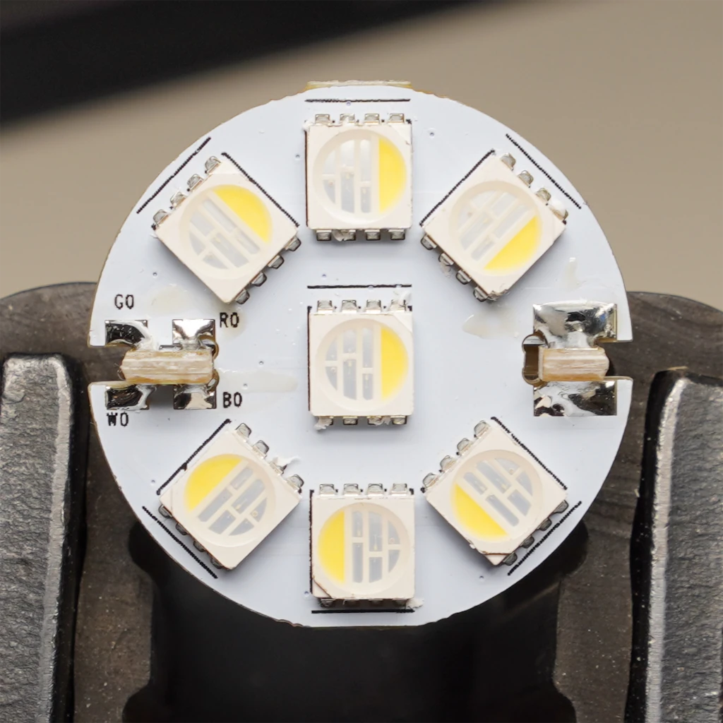
Moving west, we have two unpopulated (buttons?) followed by our pushbutton. Further west we have a 4x repeated pair of transistor
with resistor. This then leads to our LED board. The four pairs here make sense, as the LED modules are composed of
red, green, blue, and white. You can see this represented on the silk screen as R0, G0, B0, and W0.
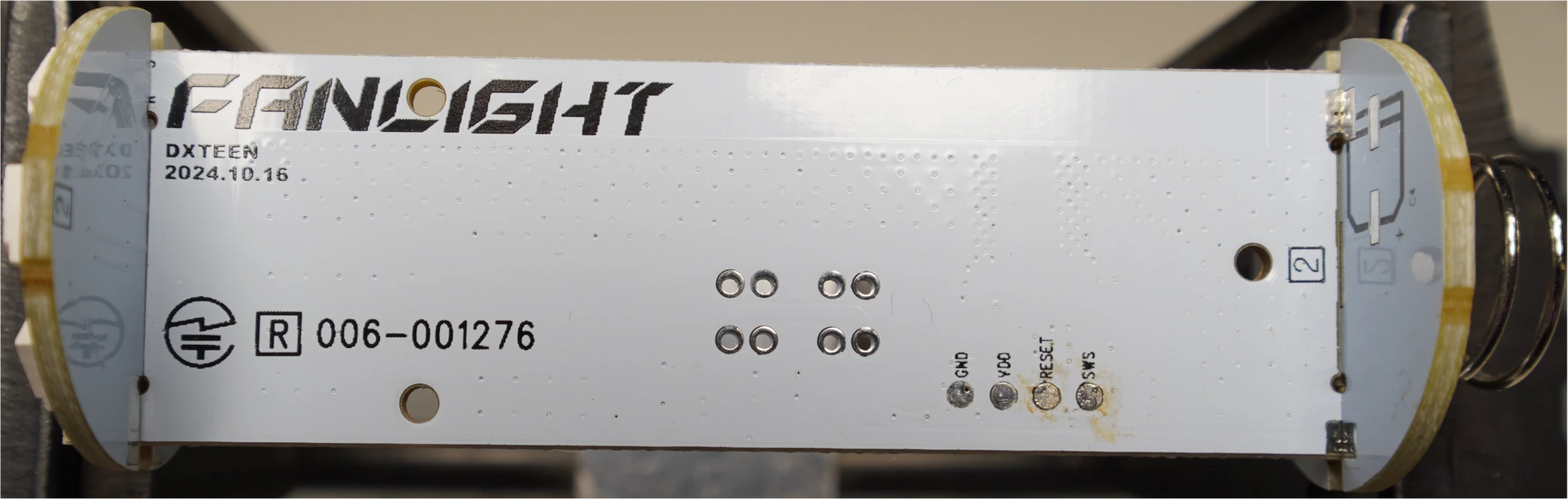
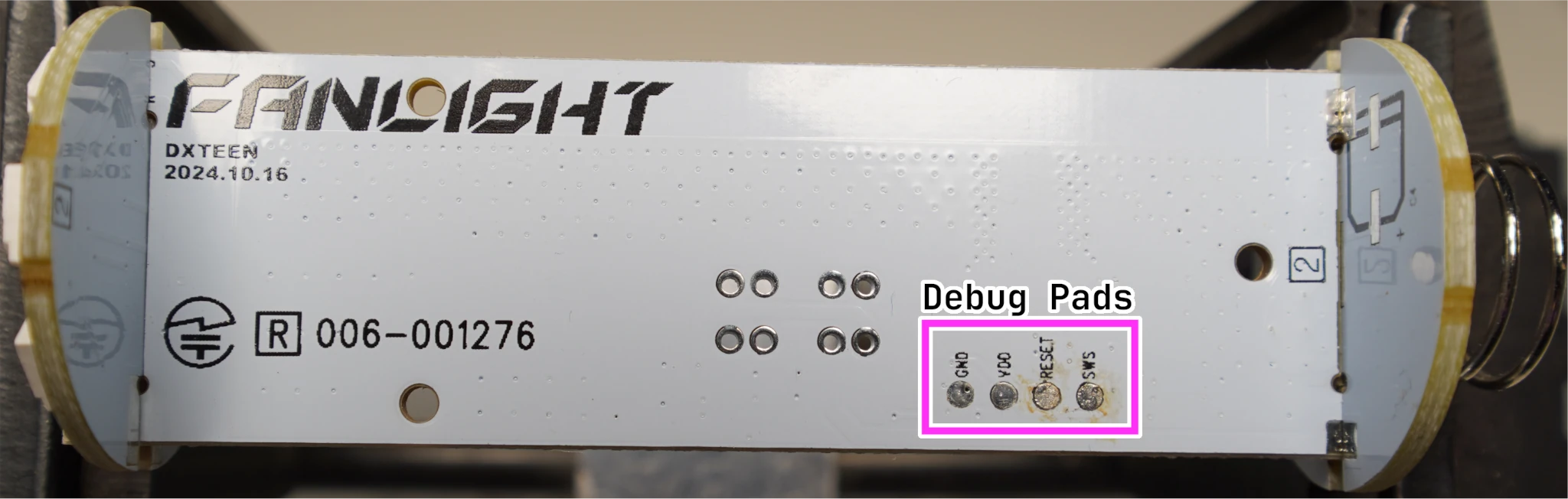
Flipping the main PCB over, we have a very interesting set of pads. These are labelled GND, VDD, RESET, and SWS. The last
one is new to me, but those prior three always spell out debug interface. If you want to interface with a device to program it,
you just about always want a nearby ground, a nominal reference voltage (VDD), the ability to put the thing in to RESET,
and then finally a line to send some data over (SWS ?).
Up Next
The next post will cover identifying the MCU, getting access to its flash, and then using that access to learn more about the device.
Thanks for reading!